-
Meta-Meta-Meta
Somehow, over the course of the past year or so, playing, writing and publishing music seems to have turned into a real thing in my world. It is now my ‘main gig’. Which means that my programming, graphics and other related activities usually have to wait until I’m done practicing. Working on my computer skills is now a hobby of sorts.
To that end I felt drawn back to a project I had started over 20 years ago. For a few years in the early 2000’s I put a lot of time and effort into it but then drifted away. Came back, dropped it, revisited it, dropped it again…. Every time adding ideas, usually in the form of private philosophical discoveries. Over time the thing had turned into an art piece with my original project at the center – like an unfinished symphony in multi-media. At this point I am accepting that this will most likely never be finished, but I also commit myself to document this strange process – like another aspect of the art project.
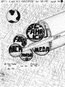
The earliest traces are found in this comic book I started to draw in 1980 – as a hobby. It was called Gefährliche Fracht nach Andromeda. Fittingly, it didn’t get finished and stops on page 40 in the middle of the story where it still hangs after more than 40 years.
This approximate ship design was reused in the 2005 video ‘Architects of Deep Reality’, which was supposed to be the first episode of a series. After I found out how labor-intensive video production is, I started to write it as a graphic novel, then a SF novel – but I really never developed the full story, just that first episode.
Around 2010 or so I picked up the idea again. This time slightly retitled ‘Engineers of Deep Reality’. The production values were higher as was the time investment. But it was a good investment, because while doing this stuff you learn so much about the software, programming and a lot more (such as the philosophy element that started to creep in, in the form of ‘Deep Reality’).
At the time the second video was made I did have a fairly good backstory and a very rough overall story arc, but just not the time to constantly keep working on it. Occasionally I would go through my materials folder to read backstory, look at images and get inspired to add a bit or two.
A few weeks ago (November 2024), while walking my dog around Griffy Lake, a totally insane ‘framing’ story popped into my head and hasn’t gone away since. One trigger was that I occasionally work on some stuff for an aging Oculus Rift VR headset. For fun I had built a full-size ‘Pilgrim’ spaceship and put it in a VR scene – this thing is almost a kilometer long and standing next to it was shocking. it would make a great game backdrop. And that is how this new phase started.
Will the game ever be finished (I rarely play computer games)? Will there ever be a cohesive story? I suspect VR will be at Star Trek holodeck level before I get anything out. But it’s fun. I learn a lot about the tools, the story, and myself. A great hobby!
And I’ll try to keep a log about my progress (maybe).
-
Building of Fringelab
It all started with Dave Weber’s drill press.
After last Winter (2016), I thought I should build a little rack to stack the firewood in our crowded basement. This was from a neat plan in Popular Mechanics magazine. Among other things it required some easy metal working. When I asked my friend Dave what drill bits would best drill through metal he said: “Here, I have this old drill press. Do you want it?” After taking the big, heavy hunk of tool home I realized that it would have to be taken apart, cleaned, oiled and then some. Over the course of a few mild days in March I carried the machine, in various stages of disassembly, outside to do the thing and then back in before it turned too wet or dark. After it was all put together again it looked (almost) like new and worked – but where was I going to put it? The large basement room, which was supposed to be a rehearsal and ping-pong facility, was already full of saws, computers, a CNC machine and wood scraps of varying sizes….
This is the point in time when I knew I needed an external workshop where I could paint, and make a mess and noise year round.
Not that it was such an original idea. A few years earlier I had toyed with the idea and even staked out a small plot next to the garden shed. But that project then fell by the wayside because it looked for a time that we might actually move and sell our house. But the stakes and the marker lines where still there – I mowed around them every time I cut the grass.

Like with every project of that size I dreaded getting started. Like the kitchen remodel from 2012, once you start you have to finish. And this one would be seen by every one of our neighbors. Nevertheless, in late May 2016 I broke ground. The first holes on June 30, 2016….

2016 turned out to be a dry Summer and work progressed quickly. My wife Monika left for a longer stay in Europe in early June while younger daughter Jasmin and I were to follow for a two week stay on July 16. The plan was to have the foundation done and concrete poured before the trip and finish after our return in August.
July 1 saw me setting and aligning posts. At that time I hadn’t really planned the rest of the structure. Rather I thought I was roughly going to follow a plan from an issue of MAKE:, which called for a 12×16 foundation. My maximum size was 12×14 feet and I hoped to adapt their plan.

July 5. If I could travel back in time I would tell myself that these holes really should be better aligned. Boards and panels are 4×8’ for a reason and your foundation should take that into account.

July 7. Looks good so far.

July 12, the evening before the cement delivery, I realize that I also need some sort of stairs. Extra digging ensues.

July 13, morning. One last picture before cement truck covers everything.

July 13, afternoon. Why would I use long 6×6” and 4×4” posts that would make it nearly impossible for the cement truck operator to navigate the chute through – in the process throwing off my careful alignment? I had finally decided to not go with the MAKE: plans. They were using some sort of arch/girder system to make sides and roof. It would have required 11 of these pieces in my structure. Each piece comprised of four large OSB side pieces cut from a 4×8′ panel by a huge CNC machine (or a hand saw?) This would have been 44 large, complicated pieces, cut by hand. Glad I abandoned that idea. I was going to go with a more normal framed structure. But I wanted to incorporate the foundation posts, at least the 6×6″ corners. And now they were knocked out of alignment.

July 13, evening. Our little puppy Joy looks at the mess (construction site and constructeur). That day, with the frantic last minute hole-digging and 90 minute non-stop concrete pour did me in. I haven’t been drinking much alcohol since a few years, but I thought I would drink a cold one that evening – and promptly passed out on the couch.

Two days later off to Germany. We’ll deal with the kinks when we come back.
Back from trip to Germany and Scotland on August 1. After measuring, I noticed that most of my posts had been seriously knocked out of alignment during the cement pour in July. I cut all of them off, except the front two 6×6” posts. Revised my plans and decided to go with a 12×12’ floor and use the front with the posts for something else.
August 28. In the past weeks I spread three tons of #3 crushed stone, built the stairs and we are now ready for the floor panels.

Finally started framing after mounting the 3/4” plywood floor panels on a revised foundation frame. To get the considerable load of heavy lumber and panels from the store to my construction site I borrowed Dave Weber’s red truck a second time. I am not an expert in any of this stuff – apparently especially not in loading studs of various lengths, 4×8’ plywood panels, and 4×4″ posts. On the way from the store, in a shallow curve on the ramp from W 3rd St onto SR37, the whole load decided to slip off the truck. Luckily, it was Sunday afternoon and hardly any traffic. Like in a movie. I felt the load shift and then saw in the rear view mirror how $300 worth of lumber literally fell by the wayside – all in slow motion. Immediately another driver stopped and started diverting traffic. Another guy jumped out of his car and started helping me collecting the dozens of pieces of lumber. Only minutes later a police car arrived and put the lights on. I thought I was going to jail. But the officer made sure other drivers were aware of the situation until everything was loaded back on. Then I found a pair of super heavy duty cargo ratchet straps (or whatever they’re called) behind the seat. The rest of the 12 minute drive went smoothly. Unloading everything did me in for the day.
While mounting the floor panels I hit my left index finger with the hammer. That was the only injury from the whole project. The finger nail turned black and has only recently fully regrown, outlining the timeline of the project.
September 5. The rear wall was the easiest to frame. In all of this I can’t emphasize enough that clamps are super important to hold stuff. Also, Dave had borrowed me his pneumatic nail gun. What a time saver.


Sepember 6. Wall framing is going smoothly. No wonder, I had the plans and measurements all worked out. I thought I would be done by October….


September 12. It was really coming along and felt already pretty stable with the OSB side panels up. At that point I didn’t know yet what was going to happen with the front wall. I thought I might pick up some random used windows and do something creative. Also at that time I realized that the way I had intended to frame the roof was not going to be strong enough. Originally I had 16’ 2×4”’s with no support in the middle. This is where the improvisation started.

September 15. After two days of building three major cross supports for the roof, I realized that there would be a little attic. To come in handy for lumber storage. Also, strong enough to hang a hammock.

September 18. Overall, one of the hardest things in the project was that I only had one pair of arms. While Zack helped me hold a few of the 4×8’ OSB side panels, I just couldn’t wait every day until he was home from school. So, clamps again. A whole other adventure were the roof panels. Somehow I had to get four full size and four half size OSB panels on the roof before the next rain (the exposed plywood floorboards started to dislike the little rain we got). 4×8’ OSB panels are not only heavy but also not exactly easy for a single person to carry. Apart from starting the project in the first place, figuring out a way to get the panels 12 feet up on the roof was probably the most challenging. I wish I had taken a picture. Where you see the ladder in the picture below, I built a guide at the roof edge using a short 2×4″ and a clamp (see, clamps again). Now I could lean the panel that was going on the roof against the side of the structure and slowly push it up, while climbing the ladder. The critical point was when the center of the panel was balancing on the edge of the roof. One step higher on the ladder, one more push so that the panel was more than half up. Then let go and it would flip up while the guide piece prevented it from sliding down the back. Kinda a dangerous and painful but it worked.
Once I had two panels up I climbed up to nail them down so I had something to sit on. Then I “transported” the rest of the panels up and was so proud of myself. I was going to beat the rain after all. I moved the ladder inside the structure and put all the tools on the roof. Now, when you use a nail gun you want to wear ear muffs to protect your hearing. Also, some safety goggles are good. So my visual and aural senses were well shielded from the outside world as I was nail-gunning away on the roof. It had been cloudy and muggy all day. I was sweat drenched and didn’t realize that a very light rain had set in – until a lightning bolt came down really close (the thunder was almost instantaneous). I was one half panel away from finishing but realized that I had to leave it at that. Luckily, I had a few of my clamps (see, again) up on the roof and was able to clamp the loose panel so it wouldn’t fly off in the storm. There was now one 4×4’ opening in the roof – but the ladder was at another spot, not where I needed it. This was when I would have screamed for help but nobody was home. I had to somehow get off the roof. Eventually, I managed to climb into the rafters and under the roof to the front where I could let myself down. Felt like a monkey.

Some of the improvised roof supports.

September 23. Finally, it was save to start storing some of the tools and materials under the new roof. Before, I spent every day half an hour in the morning, schlepping air compressor, nailer, miter saw, table saw, etc. from the basement to the construction site. And the same in reverse in the evening.

September 27. As I mentioned earlier, I was going to think about that front wall and windows when it was the right time (improvising again). Well, the right time came and I picked up three really nice looking windows plus a cool, large door at the Repo Store in Bloomington. Luckily, it was 50% off sale and with other rebates everything was less than $20. It turned out that the windows were unusable because they required a specific frame that nobody knew where to get from. I picked up three plain vanilla windows that were on sale from the hardware store. Then I started adding some (improvised) framing to the front wall. By the time I had put the panels in I needed a lot more studs – the panels need to be attached to something.

September 29. At last. Fully enclosed (sort of) and a panel blocking the entrance opening so that the cat can’t go in to poop.


October 2. I had thought that I might be done by early October. But there were so many little and big things to do, still. Since I wanted this structure to be reasonably dry, heatable and comfy (after all, computers and all sorts of electronics are supposed to be in there, not to mention a hammock for the occasional break) I decided to use house wrap. Sounds easy. But again, a single person has to be very creative to find ways to hold these large, slippery sheets in place while putting the fasteners in.

October 5. By the time I started installing the windows the usefulness of that strange front bracing had itself proven again and again. Strong enough to stand on, lay on heavy boards as scaffolding, and accommodate eventual visitors on camels or giraffes.

I had planned on a wider door because I was concerned that my CNC machine wouldn’t fit through. After some measuring I was convinced that this 30” door from the Repo Store would be fine. Actually hanging the door and making it fit was a bit nerve wrecking.

Adding some extra framing and panels to fill the gap by the door finally gave me a fully enclosed space. Another landmark. I thought I would be done within a week or two.
Even though you sometimes see buildings and trailers wrapped with this Tyvek stuff exposed for longer periods – maybe the funds ran out before adding the siding – I liked to have a little more protection from the elements. As per recommendation by my good friend and indispensable advisor Dave Weber, I decided to use cement fiber board. I borrowed the truck once again to get a load of 4×8’ plywood panels for the interior and about 50 7”x14’ cement fiber planks. I thought loading these on the truck would be easy. But they are just about 6′ longer than the truck bed. And these panels are very elastic – or “floppy”. I wasn’t worried I would loose my load like a few months ago but going through potholes the boards would swing vertically enough to touch the road. But I made it home.
The key, again, was to figure out a way how to hold these 14’ boards up with one hand, at the correct vertical distance to the previous board, and keep it straight, while being high on a ladder – and then lift the nailer and pull the trigger… My muscles were very sore for a few days (I lost about 8 pounds of weight, too.)
October 11. Installing siding on this wall was relatively easy. No openings. Just straight up. You should always start with the easiest task, right?

October 12. Cutting and installing these window frames on a good old miter saw was such a relaxing job in comparison.

October 18. Monika was already on her Europe trip but I think the kids wouldn’t have been surprised to see me walking around in the house like that.

Of course there is always something that doesn’t quite line up. That’s when you improvise.

October 29. Most of the extra crucial exterior stuff was done and I started adding insulation and interior panels. I thought about using drywall but considering that I would attach countless racks, holders, shelves and other stuff to the walls plywood panels seemed a better choice.

Wes and his assistant, my electricians from Atomic Electric, had already laid cable and installed boxes for the outlets, light fixtures and switchbox. In the picture below you can see my desperate attempt to fill some gaps with insulating foam. I guess this is easier when used with a sprayer machine of some sort but doing it through the flimsy plastic applicator that comes with the can is an insult.

October 31. The final wall was paneled on Halloween. I used wood filler in the gaps. Hoping that Atomic Electric would soon have a day to connect the power so I could stop using that long extension cord.

November 4. As long as I had been putting off starting this project, but late Summer and Fall 2016 proved to be the right time. Probably due to global warming (I regret to say) there was an abundance of warm, dry days. Rarely did I get a break due to the weather.
I didn’t originally intend to build a little roof over the entrance but I thought it would be easier to add the bracing now rather than later have to break through the siding.

At this point all the interior wall paneling was installed and painted. I found out that our local recycling center takes buckets of unused paint that you can pick up for free. Well, they had one white and one purple bucket. It was free. And it’s a nice color combo. I also added some cheap trim to the corners and the base of the walls. Just looks cleaner.

How can you not like the purple?

November 10. Major milestone. Two days earlier Atomic Electric finally had a day to swing by for the final electrical installation. This workshop is geographically at a nice sunny spot on our property but also exactly on the opposite side from where the power lines connect to the house. At first I was afraid I would have to dig a trench for the cable all around the house. But there is so much growing, especially some larger trees with big roots. It would have been a nightmare. So we decided to run the cable in a pipe along the underside of the deck in the back of the house, then along the side wall and finally through a relatively short 20’ trench under the driveway. Trenching under the driveway was hard enough. Very rocky and well compacted soil. My whole body was aching, but especially my hands. I tried to play a little guitar that evening but had no fine motor control left in my fingers.
Then Zack helped me move the workbench from the basement to the workshop. It wasn’t long now. Not October, not November, but it would be done before Christmas.

November 15. One of the last things before a full move-in was insulation in the ceiling. There had been a few colder days and the little radiant oil heater I had to keep the place warm worked fine but you could tell that a lot of heat was escaping through the ceiling. So insulation it was and since you can’t leave that exposed I needed some sort of ceiling. More improvisation ensued. But who ever looks up?

November 24. By Thanksgiving break I had most of the bigger machines and tools in the workshop. Including the CNC rig. I wanted the basement to look nice and clean for Monika’s return from Europe. While the mechanical part of the CNC setup worked, I had just updated the Dell PC I use to control the CNC machine, which has the hot name Fireball, to a newer and different flavor of Linux. The Fireball control interface needs a computer with a parallel port and these old Dells still have them (I have two of the same type, with Linux they are quite usable.) Since the workshop is in clear line-of-sight of my office there is great Wifi reception out there, but after the upgrade to Debian Wheezy neither of the Dells wanted to use Wifi. Another few afternoons of research and reinstalling. As so often, the cause was obvious once I figured it out. As much as I love Linux, but troubleshooting it sucks.

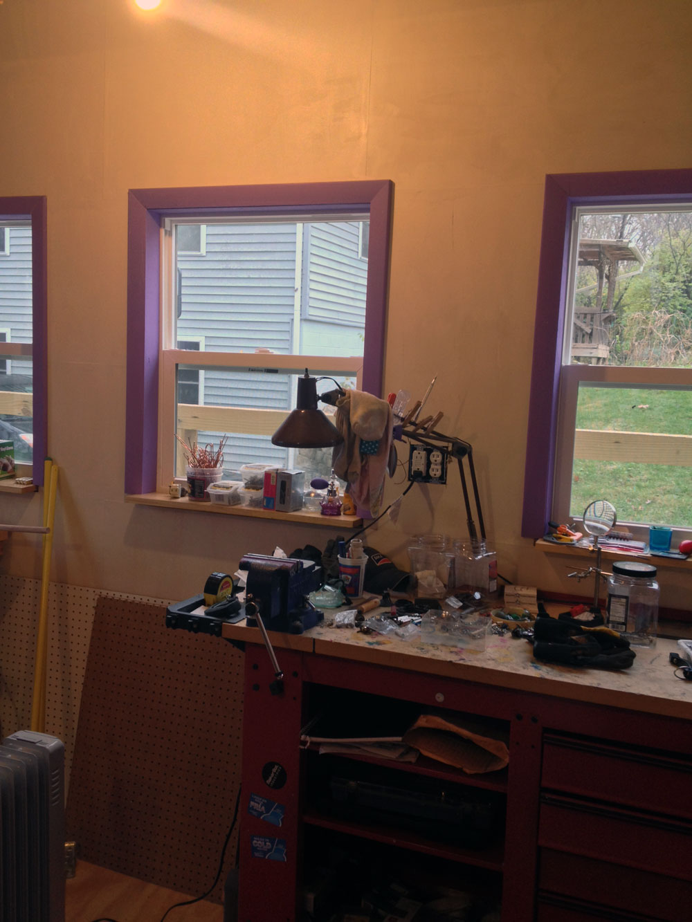
It looks nice now….

I still have to build and install lots of storage for tools, materials and all the stuff. The top of the workbench should really be free of all that crap. But for now it feels like home.
November 28. While there is still some stuff to cover on the outside, painting the outside, maybe installing that little roof over the door…. But this day Fringelab is officially done and ready for full usage.

What looks like playful decoration, the red thing under the ceiling is a hammock. Tried to nap in it, but it takes some getting used to.

November 29. And here is the simple firewood rack I started building earlier in the year, finally finished. The circle closes. The project is done, what do I do next?

-
3d Turn-O-Trope
0. Introduction

1. Basic Operation

2. The Conversion Overview

3. The Conversion Details

4. Main Components

5. Schematics

6. Arduino Code
0. Introduction
A project to convert an old record player into a controllable turntable for physical 3D animations.

What’s a zoetrope?
After typing “what is a zoetrope” into Google the first result is this:
zo·e·trope
a 19th-century optical toy consisting of a cylinder with a series of pictures on the inner surface that, when viewed through slits with the cylinder rotating, give an impression of continuous motion.
This essentially describes a looped version of a flip book. Unlike a movie filmstrip, which runs from beginning to end at a continuous speed and can show a long animation, the rotating cylinder in a zoetrope requires that the last image loops seamlessly back to the first image. That implies a rotation device of some sort.
In a traditional zoetrope the impression of a continuous animation comes about when the viewer only sees one image at a time without actually seeing the change to the next image. This is usually achieved with a mechanism that shuts the viewing slit while the change takes place. If this is done quickly enough – 12 to 16 images (or frames) per second – the viewer sees the individual images as a more or less seamless animation.
In a classic movie film projector a strip of plastic with small pictures scrolls in front of a strong light, which projects the picture on a canvas. The film strip was moved by a hand crank in early devices and later replaced by electric motors. Mechanically coupled to the rotating spools which contain the filmstrip is a small propeller-like piece which covers the light bulb while the next image is pulled in front of the light.
What makes a device like that 3D?
While the traditional zoetrope and film projectors use images that could be hand drawn or recorded with a film camera and therefore are 2D, taking this idea to 3D requires actual real objects. This real 3D version is not to be confused with modern 3D movies which use various optical gimmicks tricking the viewer to experience a more or less convincing 3D effect. The 3D zoetrope is a wonderful combination of down-to-earth basic technology with modern digital electronics.
The basic parts needed are:
– turntable capable of spinning at a constant speed
– collection of objects that display movement; for example the walk cycle of an animal (alternatively larger single objects that go in the center of the turntable and look like flowering blooms)
-light source that has an adjustable strobe frequency in sync with the turntable (emulating the little propeller from the film projector)
The old-meets-new charm here is that instead of drawing pictures by hand we use 3D printing to produce interesting objects for our 3D zoetrope.
1. Basic Operation
Connections
AC Power
- connect to regular 110V AC power
- this is the black cord coming out of the back of the unit
Strobe LED connector
- phone-style connector for external strobe pulse LED (modified to operate on 12V)
- located on the right side of the unit
USB cable
- optional connection of internal Arduino board to computer
- use Arduino software to modify and monitor code
Controls

Power ON/OFF
- main power switch; positive feedback through green status LED
- located on the right side of the unit
Control box
- located on the right side of the unit
Strobe Frequency
- when in manual mode this will allow to set the strobe frequency
Manual/Auto Mode
- in manual mode strobe frequency is not synced to turntable
- in auto mode the optical cartridge will try to synchronize the strobe signal with black markings on the bottom of the turntable
Rotation Speed
- controls the rotation speed of the turntable; about 10 – 100rpm(?)
Turntable ON/OFF
- starts/stops the turntable
Status LEDs

Status indicator LEDs
Power on (GREEN)
Auto Mode (RED)
Manual Mode (BLUE)
2. The Conversion Overview
Features of the record player:
- spins a weighted, round 12” platform at a constant speed of 33.5 or 45rpm
- motor is switched on by lifting a tone arm
- motor is switched off when tone arm has finished playing the record
The turn-o-trope
- spins a weighted, round 18” platform at constant speeds
- speeds can be set to 10-100rpm by manual control
- turntable can be switched on or off
- unit needs to trigger a strobing light source
- the frequency of the strobe can be set manually or optically synchronized with the turntable rotation
3. The Conversion Details
A turntable for a zoetrope can be built from scratch or by recycling various electronic devices that have a motor strong enough to spin discs of the required size. Smaller turntables have for example been recycled from computer hard drives. In this project I re-purposed a 30 year old record player.
After taking off the bottom cover we’re looking at these relatively simple mechanical and electronic innards.

On the left side is the mechanism that couples the tone arm with the turntable via thin metal rods. Back-right is the small power transformer which simply provides current to the motor. The audio circuitry is passive and requires no external power. Front-right is a sliding switch to select 33.5 or 45 rotations per minute. 33.5 is for LPs and 45 for singles.
For the project we will only keep the motor, everything else will have to be taken out.
The motor speed here is selected by adding or bypassing a resistor via the sliding switch.
Since the disc for the zoetrope scene should be larger than a LP, the top part of the turntable case has to be leveled so that the disc can rotate freely. This is done with various tools such as a simple handsaw, a Dremel oscillating tool and a heat gun with a cutting attachment.
Top of the turntable after some creative material removal.

Stripped of the tone arm assembly and everything else except for the motor and the metal spindle.
Unfortunately the raised plastic ledge had to be crudely cut to allow the larger disc to spin freely.
The original power transformer only had to drive the motor with 12V DC. We will use an Arduino UNO for testing and ultimately a smaller Arduino Pro Mini for permanent installation. For this we need a better option as a power supply. A small computer power supply from a recently disassembled DVD drive was available. Like most computer PSUs, this has multiple 12V and 5V feeds, a connector for an ON/OFF switch, and an LED to signal when it is powered on.

Even though this PSU is smaller than a regular PC PSU it was still a bit of a challenge to find a fitting location for in the relatively flat space inside the case.
Here, we have the new PSU on the right. The ON/OFF switch and power status LED are connected. You can also see the turntable speed control’s 10k potentiometer top-right. This replaces the fixed resistor.
The original 12V transformer is still supplying the motor at this stage.
While the speed adjustment is analog and requires no additional circuitry, the strobe light trigger and optical syncing needs a bit of computing power.
Here, an Arduino UNO is getting wired up to a photo resistor to test where and how the rotation of the disc can reliably trigger the strobe signal.
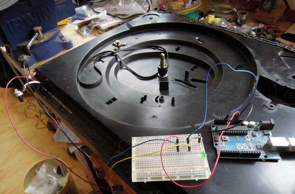
When experimenting with the Arduino, connections are usually made using short wires with wire plugs on either end. Additional external electronic components can be wired up using a breadboard.
The best spot for the optical components has been determined. This requires one white LED, which will illuminate the underside of the white, spinning scene disc. The disc is marked with thick black lines. While the disc is spinning, a photo-resistor will detect the light/dark pattern created by the consistent light source and the black lines. This will be processed in the Arduino and used to generate the automatic sync signal for the strobe.

Here, the experimental setup is slowly growing. In the black case you can spot the white LED and right next to it the small photo-resistor. Both are just stuck in there at the moment and freely movable to find the best distance from the spinning disc.
You can see how many components are connected to the Arduino or the breadboard by those gray connectors.
At this stage it is very important to use consistent wire colors to be able to trace signal and power flows.
Also, the Arduino here is connected to a laptop via a USB cable. This connection is needed to upload the program (called a “sketch”) and to monitor the sensor in the serial monitor of the Arduino software on the laptop.
To do practical testing of the illuminating LED and the photo-resistor a disc was needed. A thin plywood sheet seemed to be the most obvious material. How to cut a nice round disc? A little rig on the table saw does the trick.


But it turns out that the disc has too much mass for the motor to turn. A lighter material is needed.

Project foam board is a better choice. Easier to cut and stiff, yet very light. And since all the objects for the actual 3D scene will be 3D printed from ABS plastic, the disc won’t carry a lot of weight. The only shortcoming so far is that the material warps easily when it gets humid.
The two 3D printed circular plastic pieces in the picture go in the middle of the disc to hold it firmly on the turntable spindle and to prevent the hole in the foam board to wear out.
We are looking at the underside of the disc – which faces the illuminating LED and the photo-resistor. The ten black bars are the index stripes that are supposed to trigger the strobe. So this disc will support a ten frame animation in automatic strobe mode.
The Arduino is relatively easy to program. There is one segment of a “sketch” which sets up all the variables and initializes inputs and outputs. The main chunk is an endless loop. Everything that needs doing is done in there. At the moment all it needs to do is monitor the value returned by the photo-resistor and flash a control LED on the breadboard depending on whether that value is over/under a certain threshold. Later the code will become more challenging because several of the control buttons and the strobe trigger output will have to be served in the same program loop.
An open question from the beginning was what to use as a strobe light source. Full blown commercial strobe lights can be pretty pricey. Also it didn’t seem obvious how to trigger one from the Arduino. So for simple testing a 12V LED lamp was used. While not ideal, it could be directly connected to the Arduino trigger output. During the testing it turned out that, if anything, that light was too bright. Concerns that an LED wouldn’t be able to strobe fast enough were unfounded.
One of the things missing so far for a successful test were some 3D objects to put on the spinning disc. Thingiverse.com offers some freely download-able options. The most charming one is this set of ten walking elephants. This is how they came out of the printer.
After trimming off the “raft” (the excess plastic surface) the ten elephants perform a little break-dance before they are glued to the foam board disc.


After establishing that the basic setup actually works, all the components will have to be moved inside the case. This requires replacing the Arduino UNO by it’s much tinier cousin, an Arduino Mini Pro.
Fitting everything inside the case turned out to be much more of a challenge than expected. For one all wire connections had to be made permanent. Wire lengths had to be kept as short as possible. A location for all external control knobs and buttons had to be found. The first consideration was to have an external wired control box. This should have been removable and would have required a re-purposed SCSI cable and connectors (at least 16 wires). In the end it was more feasible to 3D print a small plastic box with a removable lid and glue/screw it to the side of the record player case. This control box now contains:

– on/off switch for the turntable motor
– potentiometer for turntable motor speed
– mode switch to set unit to run in auto strobe or manual strobe mode
– potentionmeter to set strobe light frequency when in manual modeThree status LEDs are used for visual feedback:
– green LED to indicate that the main power is on
– red LED for automatic strobe mode
– blue LED for manual strobe modeWhile the green LED is directly connected to the power supply, both the red and blue operation mode LEDs are powered through the Arduino.

At this point the photo-resistor and white disk-illumination LED where still loosely stuck in their intended location. Some scouting around in the workshop didn’t turn up anything that could be used as a mount, so a special part was designed and 3D printed. This now fits easily into the opening, is mounted securely with screws and has a lower cavity for the LED and a higher cavity for the photo-sensor. Eventually both electronic components will be glued at the ideal height.

Here the rewiring with the Arduino Pro Mini is in progress. On the far right you can also see the blue LED work light which will receive a slight rewire job. Also, next to it, the big black box with the four wires sticking out and the transparent plastic cover is a relay. While the testing setup had the strobe LED directly connected to the Arduino and thus drawing power from it, it made better sense to use the Arduino to drive the relay and then have the option later on to try strobe lights of all sorts of types and power requirements. Only the trigger impulse comes from the Arduino to the relay which then switches an independent current (if necessary from a different power supply up to 110V) on or off. While not a big component it was still a bit of a challenge to fit it in the case.
Other wiring changes included getting rid of the turntable’s original power transformer and connecting the drive motor to the turntable speed potentiometer, feeding it from the PSU. Then the PSU AC feed needed to be rerouted and safely connected to a properly tension-relieved AC cord.

Although only planned as a future extension, an FTDI breakout board was added in this version. It allows for a computer to be connected via a USB cable. This is usually only needed for software updates. But after some testing, the optical cartridge (photo-resistor/illuminating LED combo for strobe syncing) was not working consistently. So a software update was needed and the capability to send readings from the photo-resistor to the serial monitor in the Arduino software running on a connected computer.
Side view, looking at the main power switch and to the right of it the RJ12 output jack for the strobe LED. (This picture was taken before installing the USB connection)

View from top without the scene disc. The metal turntable is from the actual record player that was butchered for this project. It has a nice mass and is driven by a belt from the drive motor. On the right next to it is the optical cartridge. Here you can also see the AC power cable and the thinner USB cable.

One little detail was put off until the very end and it turned out not to be so trivial. For testing the strobe LED was always held up by hand, but for permanent operation some sort of adjustable stand was needed. The original idea was to re-purpose the stand from an old desk light but in the end this simple solution worked better. Since the strobe LED has a magnet in the back a metal rod offered itself. That way the height of the strobe LED could easily be changed. The metal rod is attached to a slot in a short PVC axis in the base. To adjust the angle the wooden slider is moved along the metal rod.
The strobe LED is connected to the turntable via a pluggable telephone wire. Since correct polarity is important when wiring an LED, a RJ12 connector was chosen.


This concluded the actual construction phase of the project on July 15th, 2017.
4. Main Components
A. Purchased Components
– Arduino Pro Mini ($12)
– VisiPort2 FTDI Breakout Board ($7)
– Auber 100A SSD relay ($20)
– Hilitchi 635 Pcs 40 Pin 2.54mm Pitch Single Row Pin Headers, Dupont Connector Housing ($16)
– Ribbon Cable – 10 wire (15ft) ($7.30)
– Gikfun Knurled Shaft Linear Rotary Taper Potentiometers ($7)
– PlatinumPower Turntable Belt ($7)
– Harbor Freight 27 LED Portable Worklight ($4)
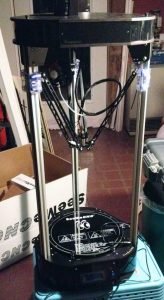
B. 3D Printed Components (printed on Rostock Max V2)
from Thingiverse
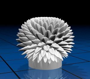
“Bloom” 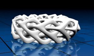
“Braided Torus” 
“Cubes” 
“Hemisphere” 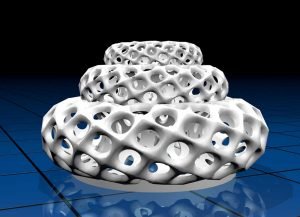
“Multitorus” 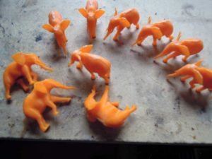
Ten Walking Elephants custom designed objects

Optical Cartridge 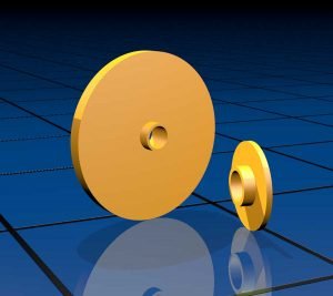
Scene Disc Holder Insert 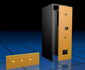
Control Box and LED Status Plate C. Repurposed Components
– JVC Record Player (audio broken)
– Power Supply from external DVD drive
– RJ12 socket from 2400kb modem
– two switches on control box
– plastic panels from Deskjet 500 printer
– several feet of 4 lead phone wire
– leftover screws and nuts from Makerbot Cupcake
D. Tools
Rostock Max V2 3D Printer – digital multimeter
– soldering iron
– Dremel heat gun
– Dremel oscillating tool
– small hand saw
– electric and manual screw drivers
– electric drill
– crimping tool
– wire cutter/stripper
– small vise
– “third hand” for holding electronics in place
– hot glue gun
– table saw
– scissors
– utility knife
– drill press
– various pliers
– forceps & tweezers
– various hex keys
– ruler
– manual & digital calipers
E. Software
– Autodesk Fusion 360 (CAD)
– Arduino (Arduino programming)
– Eagle (circuit schematics & board layout)
– Cinema 4D R15 (3D renderings)
– Blender (3D file format conversion)
– MatterControl (3D print file creation)
– Octoprint (3D printer control)
– Adobe Photoshop (image editing for documentation)
– Adobe InDesign (documentation)
– GraphicConverter 10 (image catalog)
5. Schematics
A. Turntable Main Electronics

B. Wire Header Connection Assignments

C. LED Work Light Rewire to run on 12V

6. Arduino Code
6. Arduino Code
/*
zoetrope controller

to do:
  - implement auto calibration mode for optical cartridge

v3.0  2017-7-23 include diagnostics
V2.11 2017-5-25 clean up button code (test for max & min)
V2.1  2017-5-23 added workaround for malfunctioning A2 digital in
V2.0  2017-5-20 replaced mode button by toggle switch, simplified code
V0.2  2017-5-16 added red/blue mode indicators
V0.1  2017-5-16 initial

inputs:
  (A0) strobeFrequencyPot
  (A1) cartSensor - connect to A1 & +5V and 10k
resistor A1 & GND
  (A2) modeButton

outputs:
  (5) redLED = mode 0, syncStrobe (variable)
  (6) blueLED = mode 1, variableStrobe (variable)
  (8) strobeRelay (on/off)
  (9) cartLED (variable)
*/

// user can play with these for fine tuning

// optical cartridge settings
int cartLedBrightness = 200;    // cartridge LED brightness
int sensorThresholdLow = 450;   // sensor at black spot
int sensorThresholdHigh = 500;  // sensor at white spot
int modeLedBrightness = 160;  // mode indicator LED brightness
int strobeHoldTime = 5;      // how long the strobe signal is ON

//------------------------------------------
// set pin numbers inputs

const byte potPin = 0;      // (A0) reads strobe frequency pot
const byte lightSensor = 1;  // (A1) cartridge light sensor
const byte buttonPin = 2;   // (2) number for modeSwitch

// outputs

const byte mode0LedPin = 5;  // (5) syncStrobe mode LED, red
const byte mode1LedPin = 6; // (6) variableStrobe mode LED, blue
const byte strobePin = 8;   // (8) to relay triggering the strobe
const byte ledPin = 9;      // (9)) variable power to cartridge LED
int photocellReading;
int buttonReading = 0;

// other inits and defaults

byte buttonState = 0;
byte mode = 0;  // modes: 0=syncStrobe, 1=variableStrobe
byte cycleFlag = 0;  // used in syncStrobe

// for rpm calculation in mode 1
int frameRangeMin = 10;
int frameRangeMax = 24;
int frameRange = frameRangeMax - frameRangeMin;
int potRangeMin = 0;
int potRangeMax = 1023;
int timeSlice = potRangeMax/frameRange;
int frameFrequency;
int frequencyPot;


void setup()
{
  pinMode(ledPin, OUTPUT);
  pinMode(mode0LedPin, OUTPUT);
  pinMode(mode1LedPin, OUTPUT);
  pinMode(strobePin, OUTPUT);
  pinMode(buttonPin, INPUT);
  analogWrite(ledPin,cartLedBrightness);
  Serial.begin(9600);
}

void loop()
{
  /*
  buttonState = digitalRead(buttonPin);
  Serial.println(buttonState);
  */

  // workaround for arduino not recognizing DIGITAL INPUT
  buttonReading = analogRead(buttonPin);

  //Serial.println(buttonRead);
  if (buttonReading > 1000) {
    buttonState = HIGH;
  }

  if (buttonReading < 10) {
    buttonState = LOW;
  }

  if (buttonState == HIGH) {
    mode = 1;
    analogWrite(mode0LedPin,0);
    analogWrite(mode1LedPin,modeLedBrightness);
    analogWrite(ledPin,0);
  } else {
    mode = 0;
    analogWrite(mode0LedPin,modeLedBrightness);
    analogWrite(mode1LedPin,0);
    analogWrite(ledPin,cartLedBrightness);
  }

  // decide which operations mode we’re in
  if (mode == 0) {
    // syncStrobe mode
    photocellReading = analogRead(lightSensor);

    //Serial.println(photocellReading);
    if (photocellReading < sensorThresholdLow && cycleFlag == 0)
  {
    Serial.print(“photocellReading: “);
    Serial.println(photocellReading);
    Serial.println();
    digitalWrite(strobePin, HIGH);
    delay(strobeHoldTime);
    digitalWrite(strobePin, LOW);
    cycleFlag = 1;
  }

  if (photocellReading < sensorThresholdLow && cycleFlag == 1)
  {
    //DO NOTHING
  }

  if (photocellReading > sensorThresholdHigh && cycleFlag == 1)
  {
    cycleFlag = 0;
    Serial.print(“photocellReading: “);
    Serial.println(photocellReading);
    Serial.println();
  }
  } else {
    // variableStrobe mode
    frequencyPot = analogRead(potPin);
    frameFrequency = (frequencyPot/timeSlice)+frameRangeMin;  // calculate frequency from spin time
    Serial.println(frameFrequency);  // diagnostics

    // fire strobe
    digitalWrite(strobePin, HIGH);
    delay(strobeHoldTime);
    digitalWrite(strobePin, LOW);
    delay(1000/frameFrequency);
  }
}
- Call the Police video (2)
- Comics (5)
- Construction (2)
- Deep Reality Anomalies (10)
- Documentary (5)
- Food (1)
- Fringelab (1)
- Griffy Lake (2)
- Hands-On (1)
- Home Improvement (1)
- Meta-Deep-Reality (1)
- Music (6)
- Music & Science (10)
- Peter's Money (2)
- Philosophy (4)
- Rantings (6)
- Rounding Errors (4)
- Science (9)
- SF (2)
- Solar Energy (8)
- Space (5)
- Turn-o-trope (1)
- UFO (3)
- Video & Animation (7)
- Workshop (1)
